Godot Machine technical development#
For the purposes of clarity, I will separate the issues of developing the physical design of the Godot Machine from the issues of creating software to drive it. The basic premise of the software that drove the machine remained constant throughout: a feedback-and-correction system based on visual input from a camera about an ant’s position. However, the design of the object itself went through an iterative process that borrowed a numbering system from the world of software development. Starting at version v0.0,1 each minor revision (for example, an undated actuator mechanism) would increment the design by v0.1. A major overhaul of the design (for example, a change to the structure itself) would result in a progression to the next integer, so that a major change to machine v0.4 would result in machine v1.0. This system was used to keep track of the many incremental changes and prototypical parts that were built and tested across a small number of underlying structures. The final machine that was built in this method was v3.2.
The first model (v0.0-0.1) was a rapidly-made prototype based on some sketches. Its function was to explore the mechanics of driving a polystyrene ball of approximately 180mm in any direction, and it was made of off-cuts, spare parts and old continuous rotation servos that were in the studio. Both models (the first relying on steel rollers, and the second using paper cups to rotate the ball) were unsuccessful in rotating the ball along more than one plane simultaneously, and suffered from unpredictable ‘drag’ issues caused by friction by the inactive drive wheel. It was clear that a more advanced method was required to progress.
The second model, v1.0-1.2, consisted of a concrete base of approximately 150 x 150 x 250mm, with four pressed steel arms of 1000mm length (850mm visible) emerging at an angle of around 25º from vertical, to be placed on a table or plinth. Each rod had a large surface-mount ball bearing bolted approximately two thirds of the way up, and at the extreme end, the actuating device. Resting atop the four ball bearings was a white polystyrene ball of 500mm diameter. I experimented variously with regular wheels (v1.0) and ‘omniwheels’2 (v1.1) attached to continuous rotation servos, and finally with a ‘finger’ mechanism (v1.2): a pair of lightweight micro-servos, configured to pan and tilt a small metal rod which would push the ball to rotate it. My electronics skills at this stage were still crude, and the micro-servos were incredibly jittery and ineffective at actually rotating the ball (and far better at gouging it). When I presented the work at a first critique, rather than criticise my shoddy electronics and manufacture, the panel complimented the paranoid personality the machine appeared to have. I decided to try and keep a non-wheel-based rotation with the next iteration.
I then built a more precise experimental base for the machine using laser-cut aluminium (v2.0), also designed to be placed on a table or plinth.3 Still using four ball bearings to support the 500mm ball, the chassis was designed with experimentation in mind. Each of the armatures which supported the rotation mechanisms had rows of pre-cut holes to accommodate fixing of new mechanisms at different angles. The first two mechanisms to be tested on the machine were categorically failures: laser-cut (v2.0) or 3D-printed (v2.1) ‘grippers’, powered by servos, would lift the ball from underneath and rotate it in one of four directions. The laser-cut components of v2.1 were too heavy to work with the servos, and the 3D-printed components had too much friction to work reliably. v2.1 marked the first use of 3D printing in my design work.4 v2.2 then used 3d-printed omniwheels to support the ball (designed to match the profile of the ball itself, unlike the omniwheels of v1.x). However, the omniwheels did not offer enough grip on the 500mm polystyrene ball to actually rotate it. v2.3 returned to the idea of v1.3’s ‘fingers’, but this time with laser-cut acrylic and padded rubber end-caps. However, none of the mechanisms of v2.x worked effectively. It was at this stage that I realised designing an elegant mechanism to rotate a lightweight polystyrene ball accurately in multiple planes simultaneously was a real engineering challenge. There are multiple pure robotics projects for robots that balance atop balls, etc, but most of these are concerned with the robotics element and pay little heed to the idea of a featureless ball, which I deemed essential to the Godot Machine. If the ball’s surface contained features, then the ant on the ball would have ‘landmarks’ which it could use to navigate. I spent some time working on rendering polystyrene balls with plaster to create perfect surfaces, but in the end did not find a satisfactory or repeatable method which guaranteed uniform surface, or enabled me to actually transport the balls5. I decided that a rethink of the entire system was necessary.
This iteration also marked the first design of the ‘halo’ device, an illuminated ring of white LED lights surrounding a centrally-placed webcam which connects to the controlling computer (and thus the driving devices). v2.x’s light ring was suspended above the ball from an independent support structure, much like an office desk lamp. The halo design itself served both practical and aesthetic functions: in the first instance, it provided an omnidirectional light that would illuminate the ball in order to regulate the light on the ant (much like a ring flash is often used for portrait photography). Secondly, it would confuse the ant: given that the machine was being designed in the UK, the most likely type of ant to be placed on the device would be Lasius niger, the common garden ant. This species is known to use an approximately equal, complementary combination of pheromone trails and visual landmarks to navigate,6 however, the use of trail pheromones is largely used to signal when an ant has found food, an instance that would not be applicable to an ant on the Godot Machine. A consistent light, bright, circular light source above the ant, which appears to stay in the same place, would hopefully ‘de-anchor’ any visual cues for the ant. The third function of the light was a small homage to the light ring in Dr. Strangelove.7
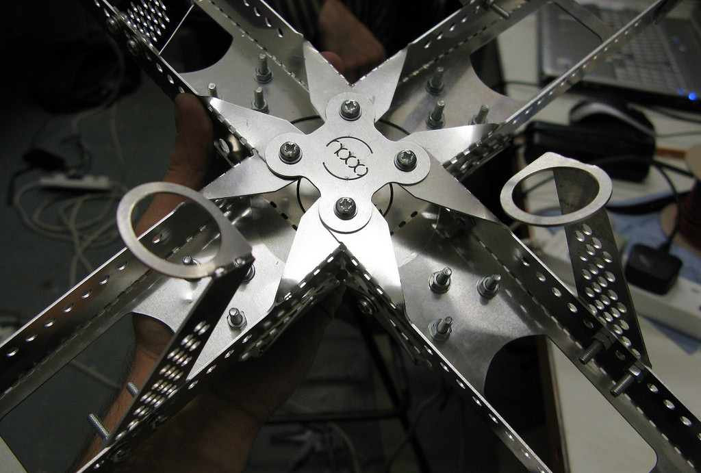
v3.x represented a major change in the machine, and my logic in designing it. Instead of separating the role of support (previously provided by ball-bearings) and actuation (the one factor I had changed so far), this version of the device rested the ball on three drive-shafts. Using three points of support instead of four – the minimum, and most stable number to support a sphere – the device was made of three pieces of identical laser-cut steel of 2mm thickness. The steel was then bent along pre-perforated lines and bolted together with M5 bolts. The pieces of bent steel overlapped each other like a camera’s aperture ring, and were in constant tension. Three stepper motors then mounted to the steel frame, and from these, brass rods would provide support to the ball. All experimentation on this model would then be with materials for the ball and the supporting rods. I bought balls with as many surface materials as possible from a nearby sports shop, and began to test these combinations. Since I had not designed the various balls, they did not factor into my numbering system.
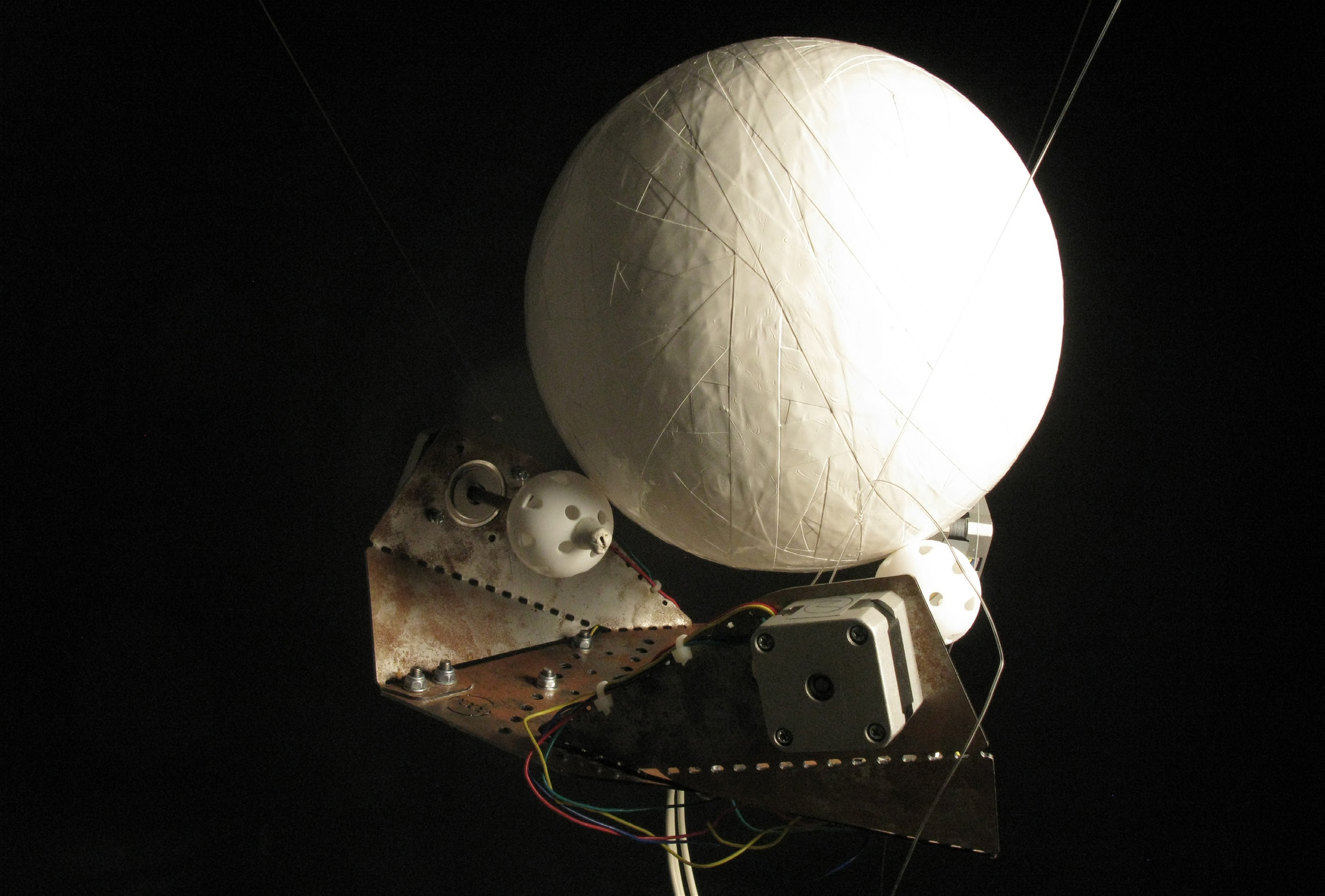
This chassis proved far more successful as a test-bed. It was also far more efficient in terms of the amount of material it required: v2.x had five different types of aluminium parts, and ten individual aluminium pieces to fit together (excluding mechanisms), whereas v3.x only had three identical steel parts. Whilst it could be tested reliably on a table-top, the design could also be suspended from a ceiling, creating the illusion that the ant really was on top of her own world, a void in space. The stepper motors were easier to programme8 than the various servo mechanisms that I had been working with. Instead of sequential loops to synchronise their movement, the steppers could be simply required a speed and a direction, and were highly accurate in their rotation. The size of the ball was reduced to between 180-250mm (depending on the type of ball being tested).

| HEADING (degrees) | MOTOR A | MOTOR B | MOTOR C |
|---|---|---|---|
| 0 | -1.0 | +1.0 | +1.0 |
| 15 | -1.0 | +0.5 | +1.0 |
| 30 | -1.0 | 0.0 + | 1.0 |
| 45 | -1.0 | -0.5 | +1.0 |
| 60 | -1.0 | -1.0 | +1.0 |
| HEADING (degrees) | MOTOR A | MOTOR B | MOTOR C |
|---|---|---|---|
| 0 | -1 | +1 | +1 |
| 60 | -1 | -1 | +1 |
| 120 | +1 | -1 | +1 |
| 180 | +1 | -1 | -1 |
| 240 | +1 | +1 | -1 |
| 300 | -1 | +1 | -1 |
At the same time as building the v3.x chassis, I built a housing for the control system. This served both practical and aesthetic purposes. Due to the practicalities of building a machine without a fixed studio space in an architecture school, and the regular transportation of the device to and from critiques, the machine and associated electronic components were subject to constant movement and dislodging. This would often have an adverse effect on the wiring, which, in prototypical form, was not permanently soldered in place. Due to my inexperience with electronics, I also kept accidentally burning stepper motor driver boards. I decided to build a housing that would enable easy diagnosis of wiring errors or broken parts, and to replace burnt boards within a few minutes. I based the distributed layout of the components on the design of HAL’s, the computer control system in Stanley Kubrick’s 2001: A Space Odyssey.9 Towards the end of the film, there is a scene where HAL is switched off one component at a time. The individual circuits are laid out sequentially, so that the logic that they control can be easily seen. My panel design for the Godot Machine used a similar logic: it laid out, in diagrammatic form, the process within the microcontroller. A USB cable carries signal from a computer to an Arduino microcontroller at the top-right. This then sends signals to three EasyDriver 4.3 stepper motor drivers, which in turn are connected via long cables to the stepper motors themselves. Along the way are a series of LED indicator lights: one on the Arduino, and one on each stepper driver indicates that it is receiving power. A pair of LEDs on the Arduino signal what it is doing at that moment: a red light indicates that the Arduino is connected to the computer, but not doing anything (‘thinking’ mode) whilst a green light indicates that the Arduino is actively sending signal to the stepper motors. The entire electronics layout is housed behind a dark blue Perspex panel with labels to indicate the components underneath, in a similar style to HAL’s fascia. Although relatively simple, the panel represents another level of diagramming within the machine.
The final design I was able to build was able to successfully rotate a sphere to any angle. v3.2 used an oversized tennis ball of diameter 180mm for the main sphere, rotated by three polypropylene attachements to the driveshafts of the stepper motors. This material combination had the right amount of friction to enable the main ball to turn smoothly and accurately in six directions by simply rotating two stepper motors at full speed in one direction, and the final one in the opposite direction (see diagram and chart). The speed of one or all of the stepper motors could also be varied in order to make the main sphere move faster or in any direction. In short, the design of v3.2 eliminated all of the engineering issues of the previous models: it presented a highly accurate control mechanism to direct the ball in any direction, at any speed (see Figure 7-54 and Table 17-2 and Table 17-2).10
I built v3.2 in the summer of 2011, at the same time as I began the ultimate stage of testing the Ant Ballet project. The final version, v3.4 assembled after a long pause in project development (assembled December 2014) used a sphere more reminiscent of a Kubrick film: a chromed plastic sphere (with the appearance of a shiny metal), and black tennis balls as actuators. This has yet to be exhibited, for reasons that are discussed in Chapter 1.
-
When programming, the number 0 is normally the first number. ↩
-
Wheels designed to rotate in one plane, but allow movement in another. Onmiwheels are common on factory floors or on contemporary self-driving robots. ↩
-
The use of laser-cut aluminium was influenced by the work of students in the Bartlett’s Unit 14: Subomi Fapohunda and Dave DiDuca. ↩
-
I had taken a course in 3D printing run by Matt Shaw (later of ScanLab) and Justin Goodyear of the Bartlett. ↩
-
I built several 500mm polystyrene balls which were rendered with plaster, and subsequently became damaged or destroyed through transport. ↩
-
Sophie E. F. Evison et al., ‘Combined Use of Pheromone Trails and Visual Landmarks by the Common Garden Ant Lasius Niger’, Behavioural Ecology and Sociobiology 63 (2008): 261–67, doi:10.1007/s00265-008-0657-6. ↩
-
Note that at the time of production, 3D printing in nylon was considerably more expensive (and harder to attain) than it is today. The Bartlett 3D printing service charged per cubic centimetre of the rectilinear volume of anything printed. In order to reduce this cost, the halo was printed in three identical parts, printed close together, then later assembled using the same type of bolts as in Godot Machine v2.x. Having a background in product design, and having been previously subject to the limitations of injection moulding and other traditional manufacturing techniques, it was my ambition to ensure that every 3D printed design I made utilised the potential of the technology to do more than simply creating parts that could be injection moulded, with interlocking components or integrated mechanical systems: hence, in v2.x, the printing of one-part omniwheels and fully integrated articulated lever systems. When printing more straightforward components such as the halo, the parts would always be printed inside a bounding ‘box’ with wall thickness 0.75mm, with large holes at either end for the removal of excess powder. This provided a means to ensure that smaller components were not lost from the densely-packed array that I would always print at one time. ↩
-
Although easier to programme, they did require separate driver boards. I will elaborate on these later. ↩
-
Stanley Kubrick, 2001: A Space Odyssey, Film (Metro Goldwyn-Meyer, 1968). ↩
-
Up to the highest speed of the motors – which by far exceeded the top speed of even the fastest Lasius niger. ↩